↓
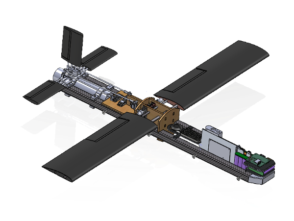
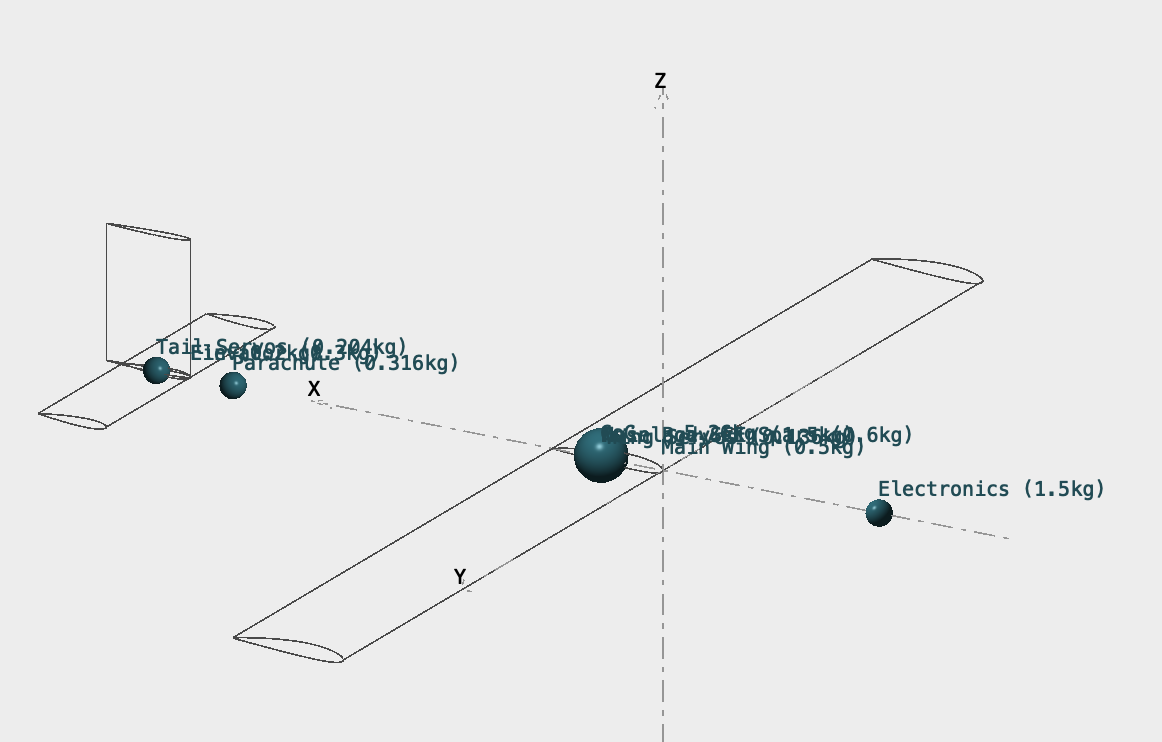
Weight: 5.1 kg
Dimensions: 120 x 120 x 45 cm
Wing Span: 118 cm
Wing Chord: 14 cm
Wing Airfoil: Clark Y
Tail Span: 32.6 cm
Tail Chord: 7.4 cm
Tail Airfoil: NACA 0012
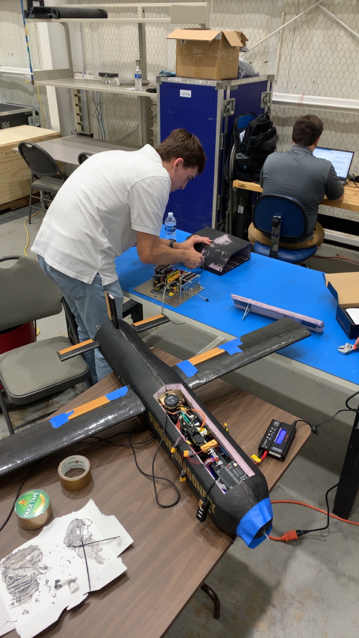
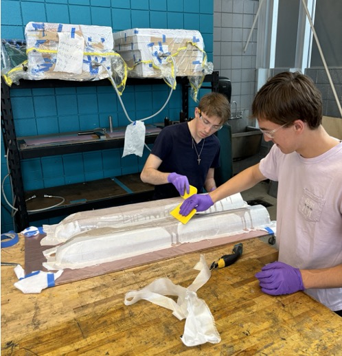
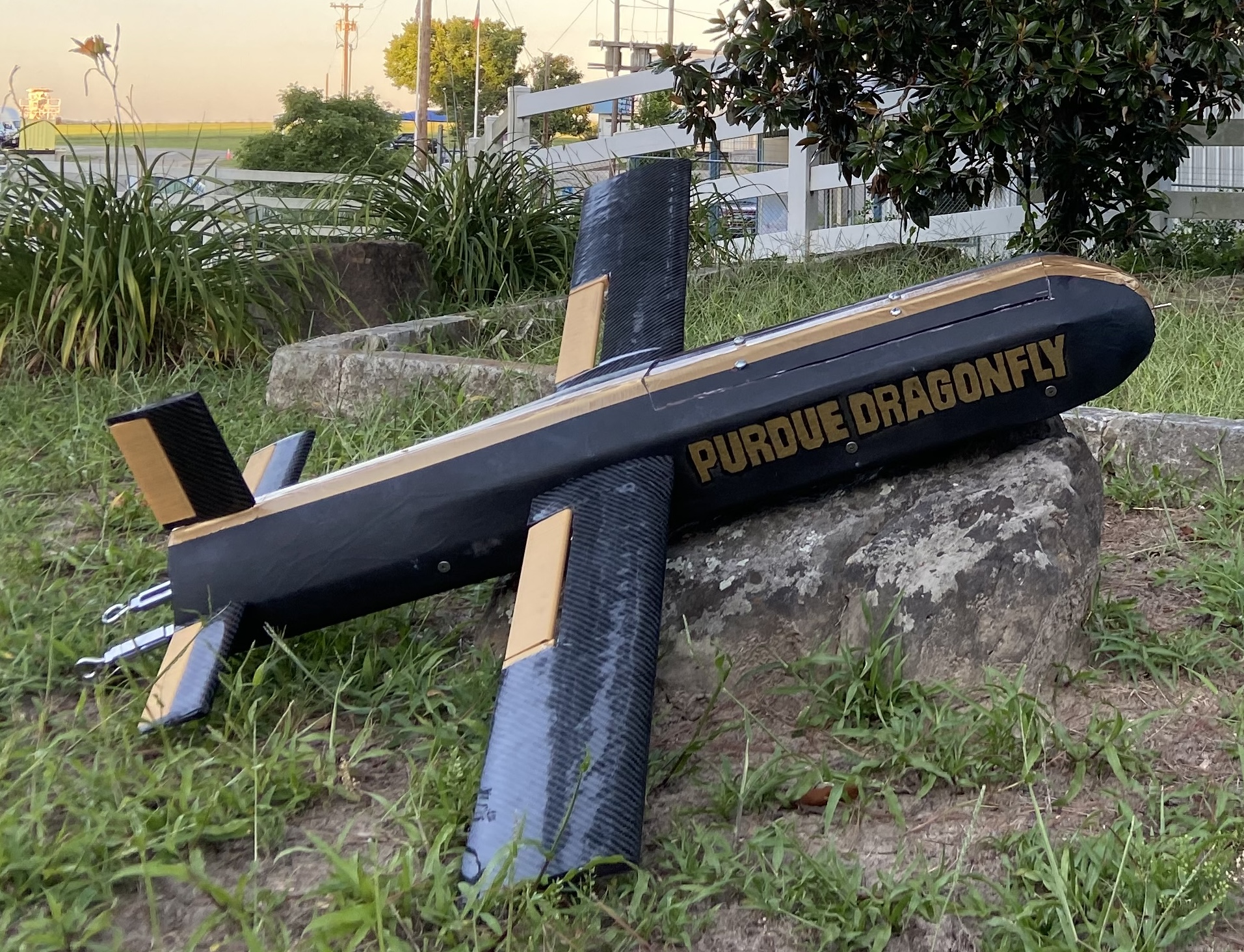
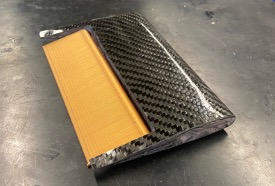
The main structure of the airframe of the V2 vehicle are two, 1" carbon fiber spars. This is then enclosed by a composite (2 cm foam and 3 layers of fiberglass) shell. The foam acts as insulation in the extreme Antarctic environment and the fiberglass creates a hard shell to protect against external objects, provide extra stiffness, and is RF clear for GPS communications.
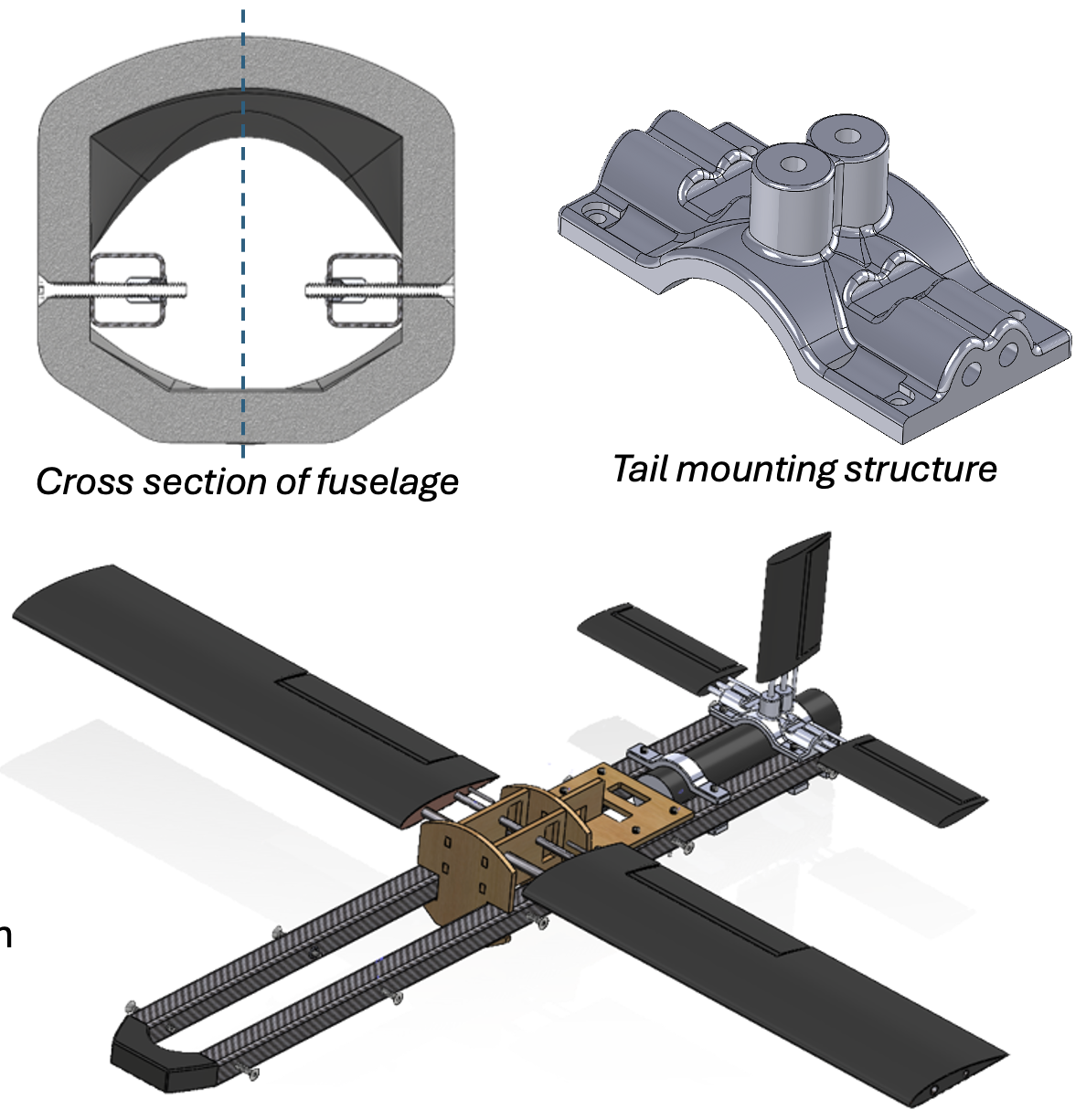
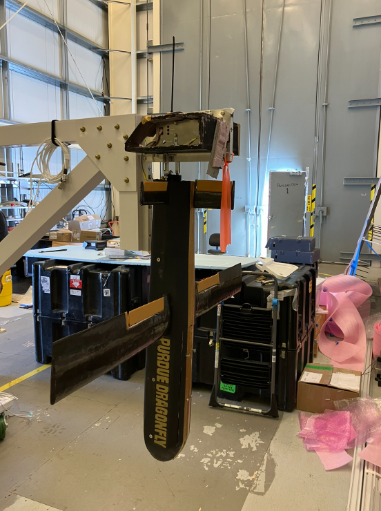
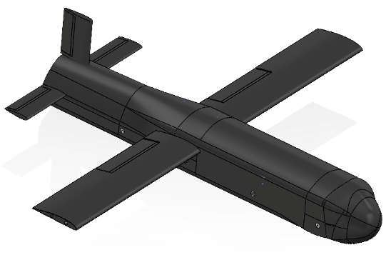
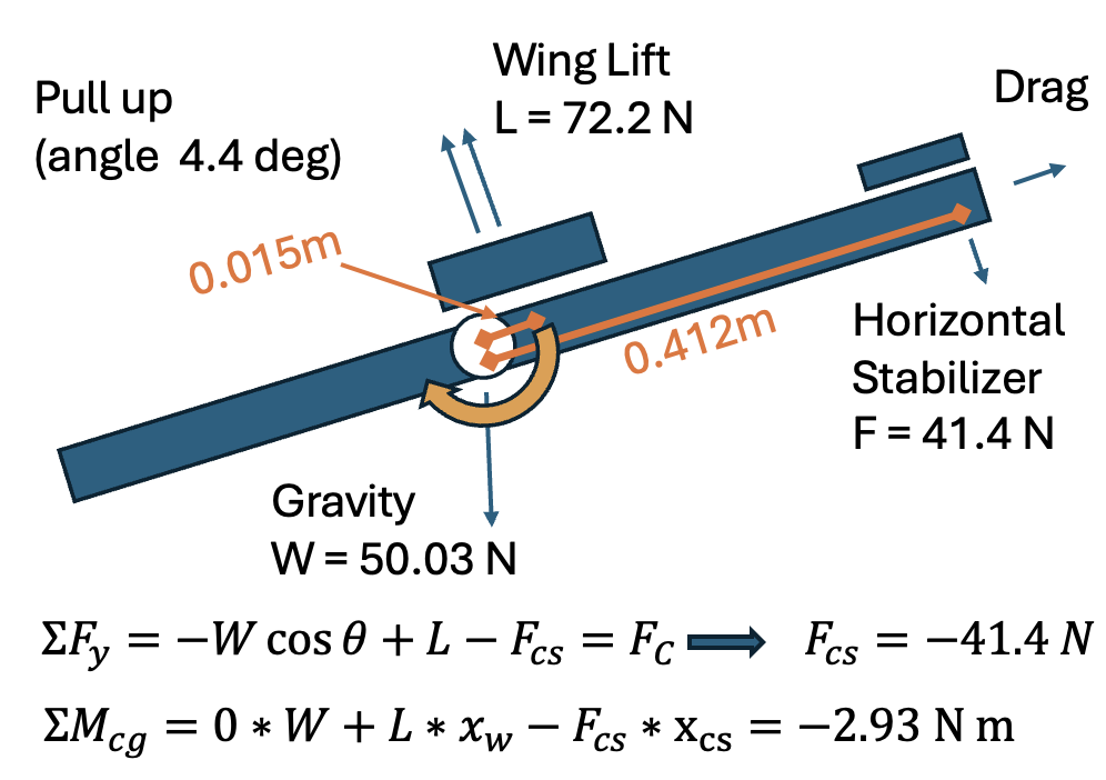
The tail is a traditional style with two horizontal components and a vertical components. These were sized initially based on volume coefficients of standard fixed wing aircraft. The size was then refined to ensure control authority is maintained during the pull up maneuver, thick enough structure to withstand loads, but thin enough to not have too big of a negative affect on longitudinal static stability.
Horizontal tail
Vertical tail
To actuate the tail control surface, it was necessary to create a mechanism that includes a servo, push rod, and lever arm. This constraint is due to the parachute being in the rear of the aircraft and there not being enough room to put the servos directly in the tail and actuate with small push rods (as typically used in hobby RC aircraft) nor adjacent to the tail control surfaces and actuate using torque rods.
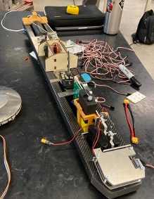
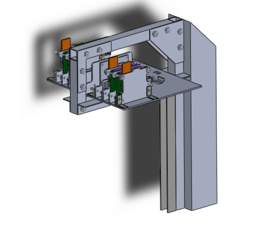
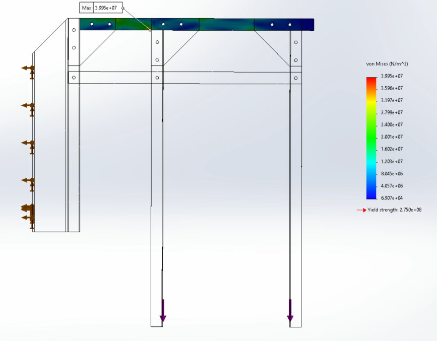
The gondola mount is the physical and electrical interface between the NASA gondola and the vehicle. It is constructed using 6061 T6 Aluminum and 1/16" laser cut Aluminum braces. Within this frame, there are 4 batteries which supply extra heat to the vehicle before deployment, and a control panel which processes the NASA signal and retracts two linear actuators to release the vehicle.
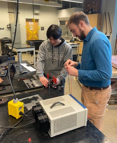
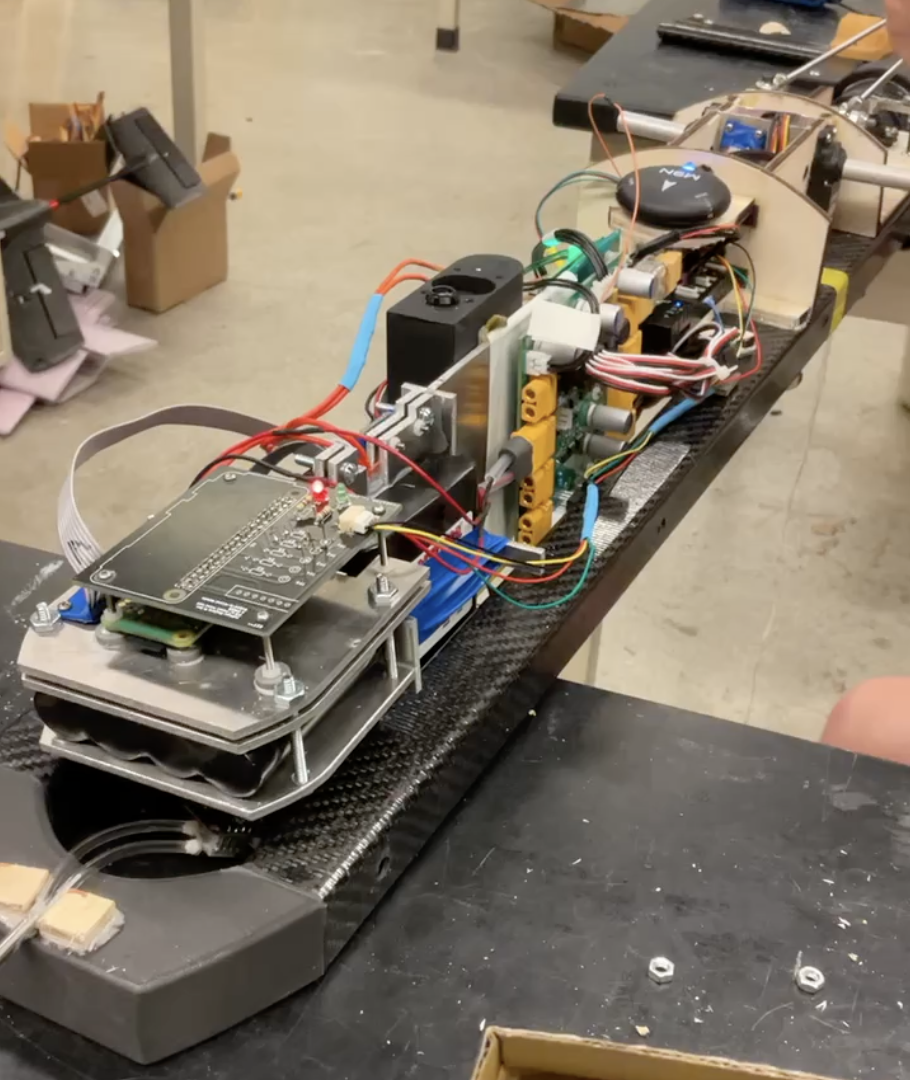
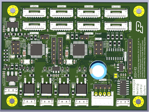
The heating sytem consists of heaters, thermistors, a microcontroller, batteries, and aluminum plates. The microcontroller controls a simple control system between the heaters (output) and thermistors (measure). Aluminum plates are used for conductive heat transfer from the heaters to the electronic components in the near vacuum of 120,000 ft when there will be little air for thermal transfer through convection.
The diagram to the left shows the overall electronics schematic. This depicts how different components and PCBs interact with each other between the vehicle and the gondola.
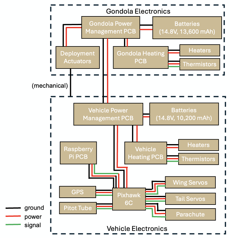
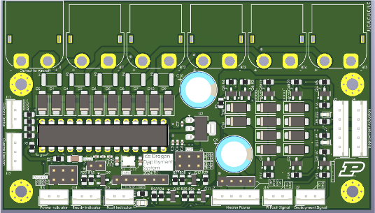
Similar to V1, Raspberry Pi Zero and Pixhawk 6c are being used together as flight controller. To determine altitude, we rely on the pressure reading from a Pitot tube along with GPS Data. Pixhawk 6c has internal IMUs and barometer, we can rely on IMU to achieve stable flight and set our attitudes and the magnetometer will provide heading.
Stability and controllability analysis was performed using XFLR5. Longitudinal stability (measured by static margin) and lateral/directional stability were studied in order to ensure that the system could maintain static and dynamic stability throughout flight.
Finite element analysis was performed on the gondola to determine whether the system would be able to withstand a 10g shock and not prematruely drop the node. This was especially important for the first FLOATing DRAGON campaign because the node could not be dropped prematurely over populus areas of New Mexico. FEA was presented at the structural design review with NASA in April 2023 and again revisited in the flight readiness review in July 2023.
Hand calculations, physical tests, and finite element analysis were performed on vehicle components to ensure that the structures would be able to maintain forces endured during the mission. This includes wing bending, enduring gusts, and shock from the parachute deployment.
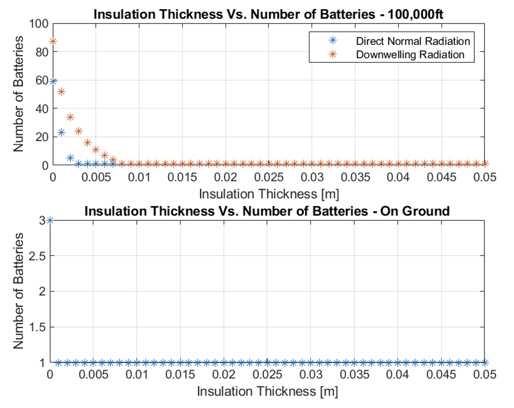
To correctly determine how many batteries and how much insulation should be used, the team conducted a trade study on this tradeoff. Theoretically, there would be a number of batteries and insulation thickness that minimizes weight. As it turned out, due to sun radiation at altitude, the vehicle would actually have a cooling problem. However on the ground in frigid Antarctic temperatures, insulation and batteries would be necessary to keep the electronics within operating temperature ranges.
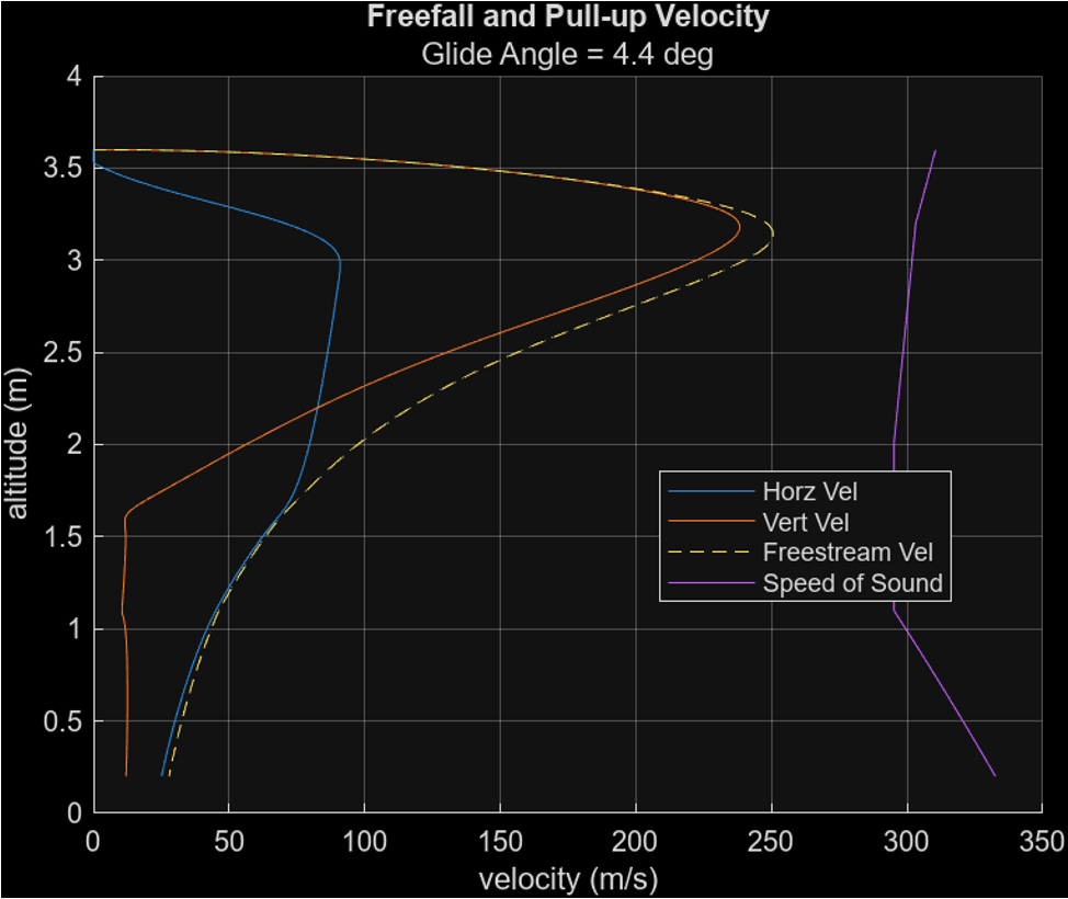
To ensure that the vehicle never goes trans or supersonic while also having enough control authority to perform any manuevers necessary, analysis was done using MATLAB and XFLR5 to characterize the vehicle's flight.
(click on an image below to get started)