↓
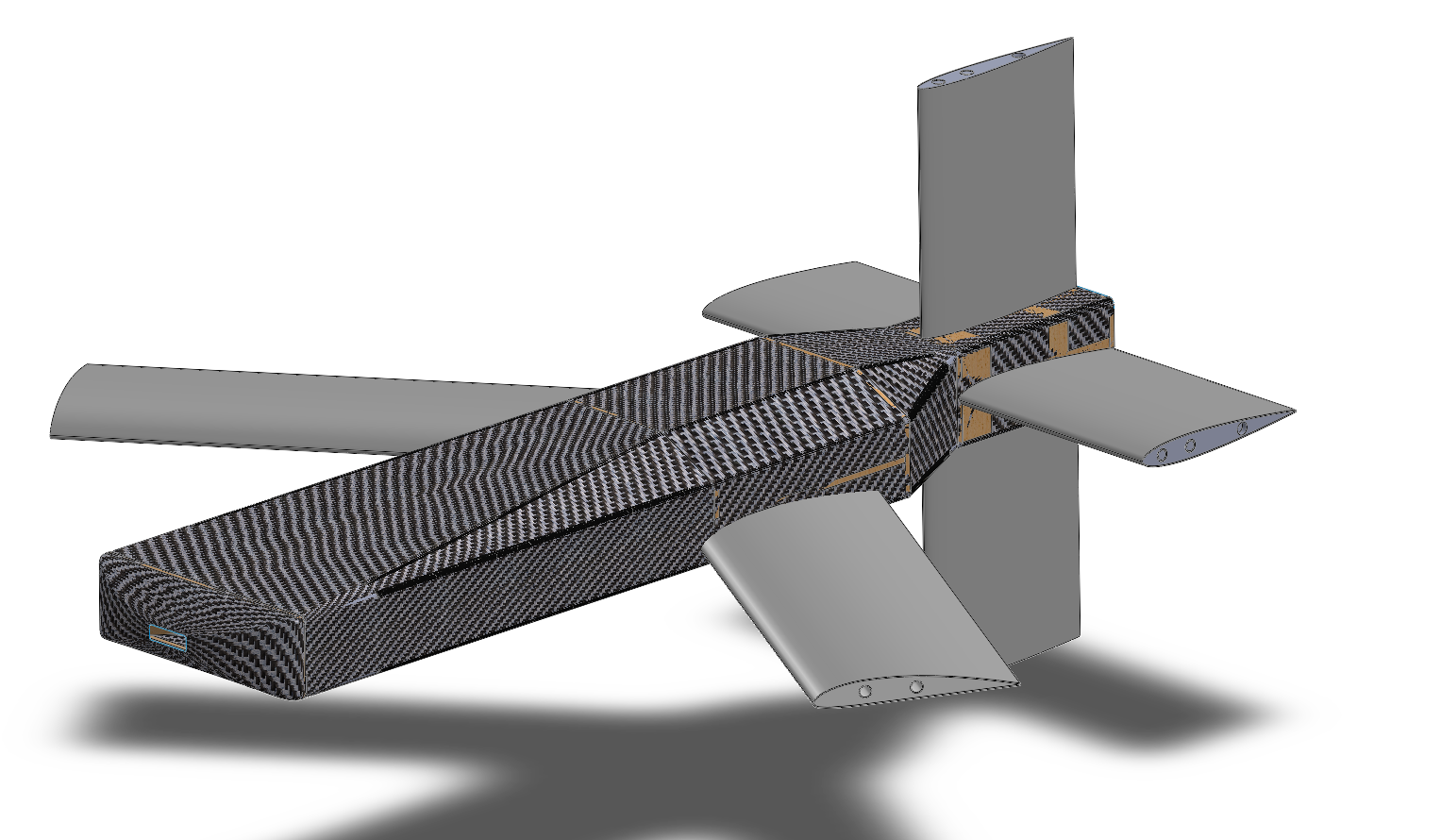
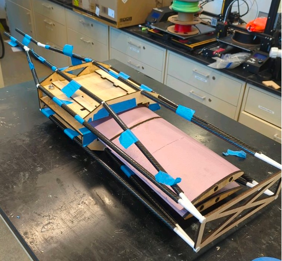
Weight: 9.5 kg
Dimensions: 120 x 45 x 45 cm
Wing Span: 140 cm
Wing Chord: 20.5 cm
Wing Airfoil: Clark Y
Tail Span: 60 cm
Tail Chord: 20 cm
Tail Airfoil: NACA 0012
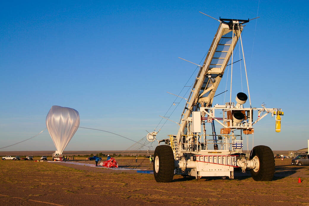
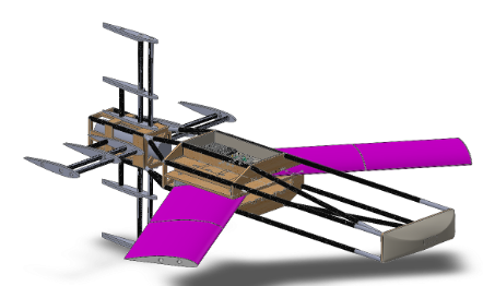
In the first stage of descent, the node dives through the upper atmosphere. To slow its decsent to subsonic speeds and maintain the nose pointed down, the cruciform tail control surfaces act as an airbrake. The controls team is working on an algorithm which will be able to allow for the controlled descent.
Once the node passes through the high winds in the upper atmosphere and reaches air where lift can be achieved, the wings deploy. The wings are stowed in the fuselage for aerodynamic purposes in the dive but fold outwards for the glide. There are no control surfaces on the wings, and the node is entirely controlled using the tail control surfaces.
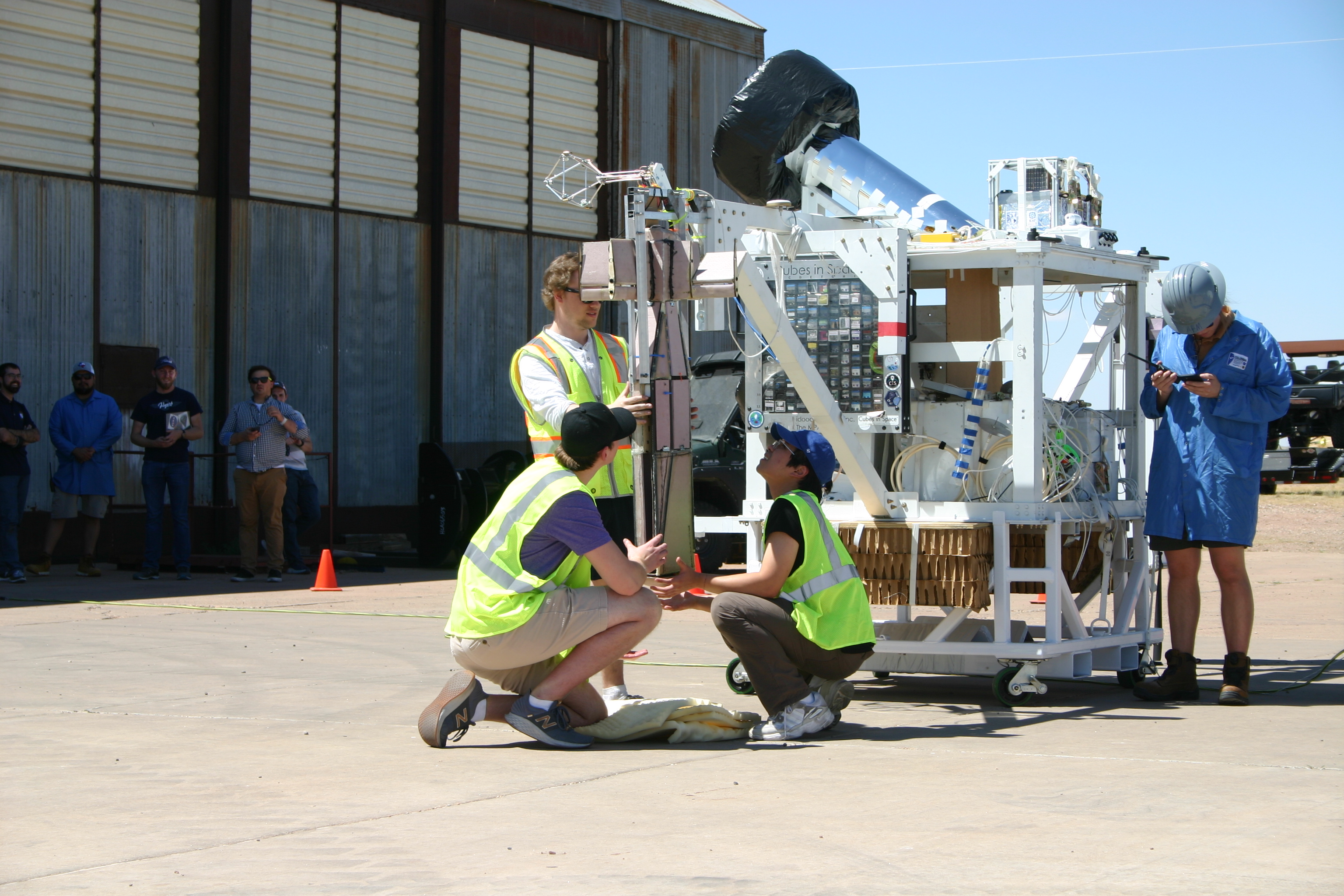
To release the node from the gondola, four linear actuators retract when a signal is received from the gondola. This system is currently very heavy and complicated, and will be redsigned for the ICE-DRAGON campaign.
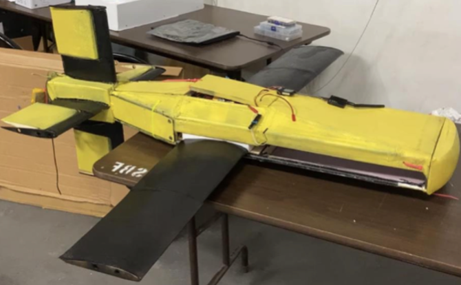
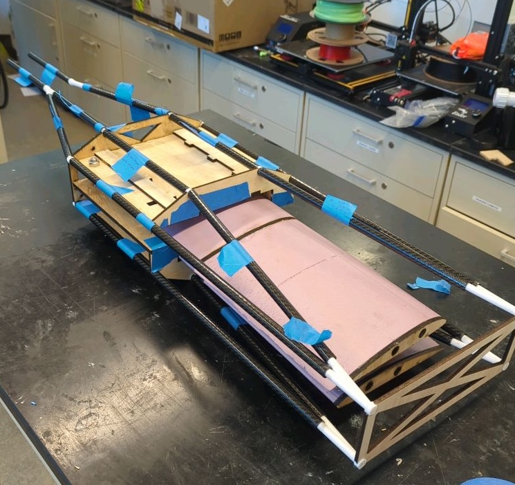
The entire airframe of the Dragonfly V2 is composite-based. Composites were chosen for their superior structural qualities, ease of use in prototyping, and low weight. Composites used include carbon fiber rods, fiberglass reinforced foam, and carbon fiber reinforced onyx.
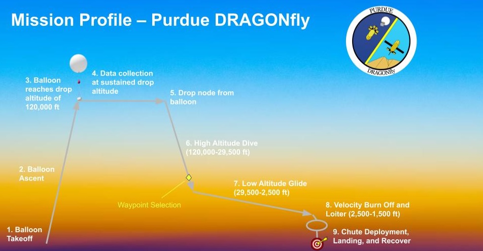
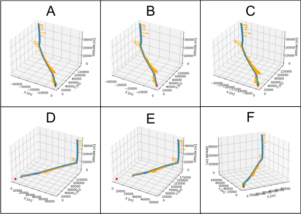
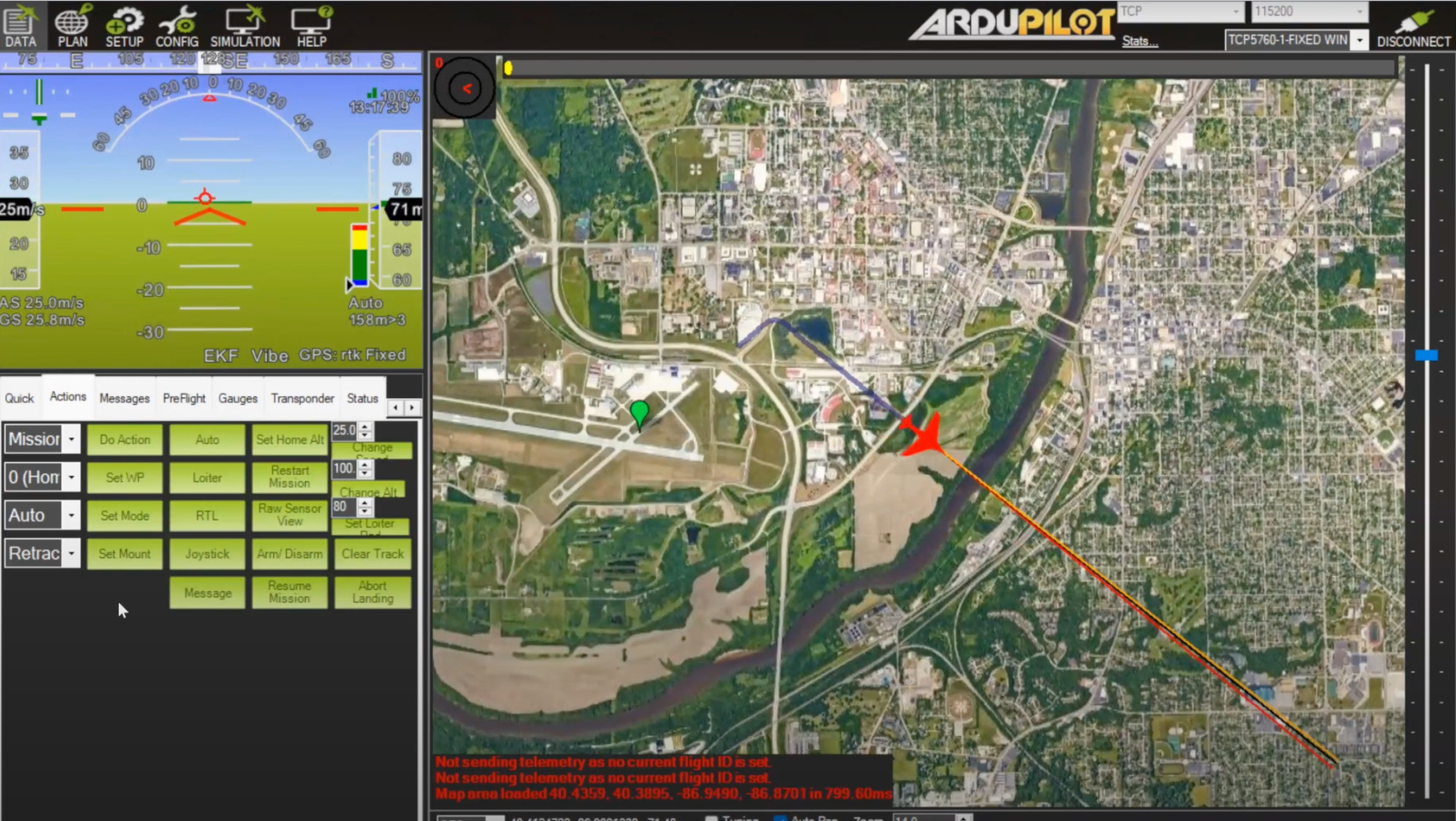
An on-board raspberry pi performs an algorithm for waypoint selections, deployment armings, and dive-glide phase transitions. In the image to the left, the waypoint planning algorithm recognizes routes A, C, and F as feasible as they each reach the target destination. Route F is ultimately selected due to its increased time efficiency.
The Dragonfly utilizes an onboard Pixhawk 6C as a flight computer. This stabilizes the node with integrated IMU sensors and provides GNSS data to the Raspberry-Pi (which performs algorithm). Ardupilot autopilot is used for the dive and glide phase stabilization. The MAVSDK protocol is used for communication between the Raspberry Pi and Pixhawk.
Computational fluid dynamic analysis was performed on the entire vehicle and different wing/tail orientations. Entire vehicle analysis focused on the drag produced by fully deflected air brakes and other aerodynamic properties. Wing/tail orientation analysis focused on the affect of different combinations of wing and tail placements and how they would interact.
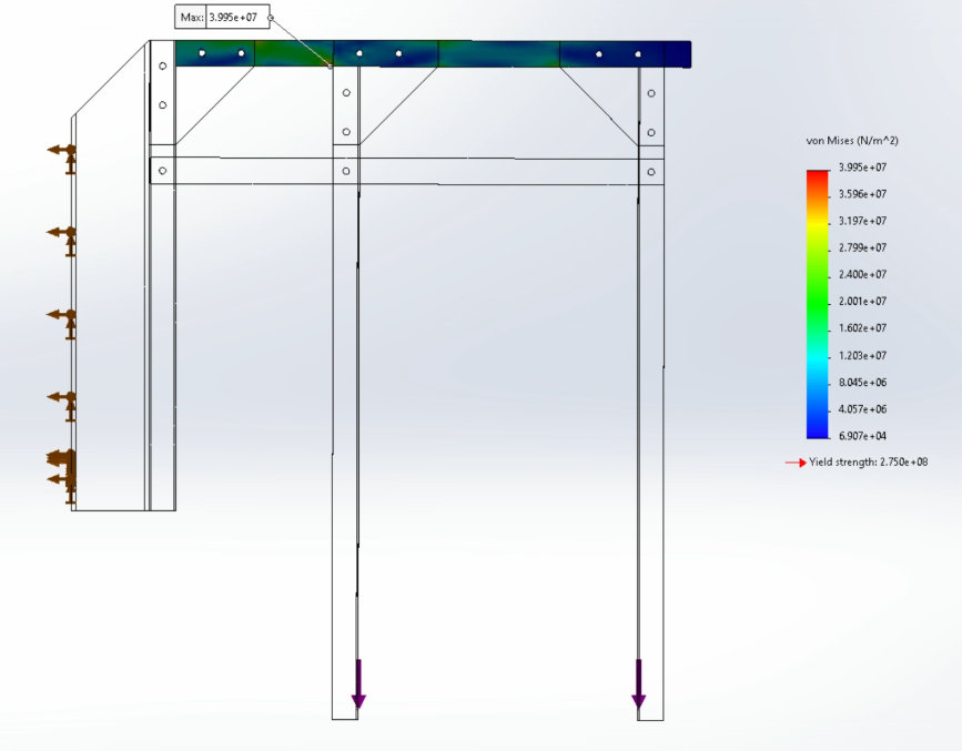
Finite element analysis was performed on the gondola to determine whether the system would be able to withstand a 10g shock and not prematruely drop the node. This was especially important for the first FLOATing DRAGON campaign because the node could not be dropped prematurely over populus areas of New Mexico. FEA was presented at the structural design review with NASA in April 2023 and again revisited in the flight readiness review in July 2023.
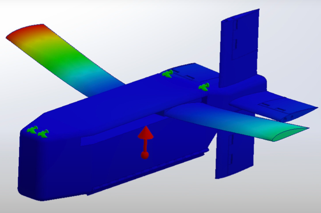
Finite element analysis was performed on the vehicle to ensure that the structures would be able to maintain forces endured during the mission. This includes wing bending, enduring gusts, and shock from the parachute deployment.
The wing span and chord were optimized using algorithms on structural bending and lift during design cruise and stall speed.s
Stability and controllability analysis was performed using XFLR5. Longitudinal stability (measured by static margin) and lateral/directional stability were studied in order to ensure that the system could maintai static and dynamic stability throughout flight.
Wind tunnel tests were performed in the Boeing Wing Tunnel at Purdue. These were preliminary tests performed in Fall 2022 to demonstrate the drag produced by the airbrake.
(click on an image below to get started)